A new printing technique places perovskite photodetectors on contact lenses, and AI upscaling turns 100 sparse pixels into an eye-tracking interface for robotic control.
(Nanowerk Spotlight) Turning a contact lens into a camera-like sensor that captures and interprets light patterns requires solving two problems at once. The first is fabrication: how to deposit an array of photodetectors onto a steeply curved substrate just millimeters across, quickly and without expensive lithographic equipment. The second is information: even if the array can be printed, the limited real estate of a contact lens restricts it to so few pixels that the raw data alone cannot support useful visual tasks.
Previous attempts have tackled these challenges separately. Inkjet and electrohydrodynamic printing can pattern perovskite photodetectors at microscale resolution, and perovskite-based smart eyeglasses for non-camera eye tracking have shown that such materials can function in wearable form factors. But these deposition methods struggle with curved geometry and require extensive process tuning for each substrate shape.
Extrusion-based approaches tolerate curvature better but produce features too large for dense pixel arrays. Meanwhile, computational techniques such as single-pixel imaging and patterned illumination can extract information from minimal hardware, but they rely on sequential measurements too slow for real-time wearable use.
A study published in Advanced Functional Materials (“Meniscus Pixel Printing for Contact‐Lens Vision Sensing and Robotic Control”) bridges both problems in a single platform. The researchers introduce a printing method simple enough to place perovskite photodetectors on a curved contact lens in about 1 second per pixel, then pair it with a deep-learning model that transforms the sparse sensor output into visual information rich enough to track eye movements and control a robotic arm.
The technique, called Meniscus Pixel Printing (MPP), uses a micro-nozzle pipette to bring perovskite ink into brief contact with a substrate, forming a self-confined liquid bridge between the tip and the surface. Earlier work on meniscus-guided 3D printing of perovskite nanostructures demonstrated that such liquid bridges can direct crystallization with high spatial precision, but those methods relied on continuous trajectories that limited throughput.
MPP instead uses a rapid touch-and-release cycle, where capillary forces and interfacial tension govern how much ink transfers, restricting deposition to a tightly defined region. Each 200 µm pixel prints within roughly 1 second, with no lithographic masks or specialized equipment.
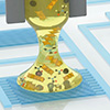
(a) Schematic of the Meniscus Pixel Printing (MPP). (b) Optical images of the MPP process with a 100 µm nozzle on the substrate. The scale bar is 200 µm. (c) Conceptual illustration of dwell time-dependent dot sizes control. (d) Schematic of the Solution-mediated perovskite crystallization pathway following MPP. (e) The optical images show the crystallization during the annealing process. The scale bar is 5 mm. (f) SEM image of the resulting perovskite layer. The scale bar is 10 µm. (Image: Reproduced from DOI:10.1002/adfm.202531981, CC BY)
The active material is methylammonium lead iodide (MAPbI₃), a member of the perovskite family, a broad class of crystalline materials whose shared atomic arrangement gives them unusually strong light-absorbing and charge-carrying properties. MAPbI₃ is prized for its strong visible-light absorption and compatibility with low-temperature solution processing. Unlike conventional semiconductors such as silicon or cadmium sulfide, it dissolves readily in common solvents, making it well suited to printing-based fabrication.
The researchers optimized the ink by blending two solvents, DMF and DMSO, at a 3:1 ratio to balance evaporation speed: too fast and the crystals form small and riddled with defects; too slow and solvent residues impede charge transport. The tuned formulation roughly doubled the photocurrent and produced the uniform, reproducible dots used in the final contact lens device.
Two parameters control dot size: the dwell time during which the nozzle stays in contact, and the retraction speed. Together they yielded diameters from about 200 to over 700 µm with high consistency. For the contact lens array, the team selected a 300 µm dot size. MPP also works on steeply curved surfaces: the researchers printed stable pixels on substrates with a radius of curvature of 8.6 mm, comparable to the human cornea, and on slopes as steep as 63.3°, without any equipment or process changes.
Using MPP, the researchers built a 10 × 10 photodetector array on a circular indium tin oxide substrate 8 mm in diameter. A photocurable resin encapsulated the printed dots to protect them from moisture and mechanical damage. The device responded to red, green, and blue illumination. After two months of ambient storage it retained about 92% of its initial photocurrent, and lead-leakage tests under cyclic mechanical pressure found no detectable lead above 2 parts per billion, an important threshold for any device intended to sit on the eye.
A hundred pixels, though, capture far too little spatial detail for meaningful visual tasks. Increasing the physical pixel count is impractical on a lens this small, so the researchers turned to computation. They trained a Super-Resolution Generative Adversarial Network (SRGAN) to infer the missing information.
The network has two competing halves: a generator that attempts to reconstruct a plausible high-resolution image from the sparse input, and a discriminator that judges whether the result looks realistic. Through iterative training on 35,000 augmented samples derived from seven basic geometric shapes, the generator learns to recover edges, curves, and structural details that the hardware cannot physically resolve.
The model upscaled 10 × 10 sensor inputs into 80 × 80 representations. Tested on handwritten digits it had never seen during training, it achieved 97.2% classification accuracy at about 0.03 seconds per inference on a standard laptop processor. Rotating arrows and translating text confirmed that it reconstructed spatial information from live optical signals rather than matching inputs to stored templates.
For the robotic control demonstration, an artificial eye module driven by servo motors generated movements in eight directions plus blinking. Frame-by-frame shifts in the light pattern on the lens were analyzed to classify gaze direction into eight movement commands (up, down, left, right, and four diagonals) plus a blink command that triggered gripping and releasing.
To test the system under more constrained conditions, the researchers cut sensor resolution from 10 × 10 to 5 × 5. Raw tracking accuracy across nine movement classes fell to 88.4%, with most errors in diagonal directions. After super-resolution upscaling, accuracy reached 99.3%, and the arm completed pick-and-place tasks guided entirely by eye movement.
That a mask-free, room-temperature process can now place functional optoelectronics on a contact lens and pair them with real-time AI marks a tangible step toward wearable vision interfaces. If future iterations can increase pixel density, miniaturize the readout electronics, and validate biocompatibility over extended wear, such platforms could serve as lightweight alternatives to head-mounted XR displays and hands-free controllers for assistive robotics.
For authors and communications departmentsclick to open
Lay summary
Prefilled posts
ORCID information
Im Doo Jung (Ulsan National Institute of Science and Technology (UNIST))
, 0000-0003-0883-1848 corresponding author
Nanowerk Newsletter
Get our Nanotechnology Spotlight updates to your inbox!
Thank you!
You have successfully joined our subscriber list.
Become a Spotlight guest author! Join our large and growing group of guest contributors. Have you just published a scientific paper or have other exciting developments to share with the nanotechnology community? Here is how to publish on nanowerk.com.