An elastic metamaterial can do math by directing motion through tiny pathways, showing how materials might one day handle simple computing tasks without electronics.
(Nanowerk Spotlight) Computing hardware has always separated the physical world from digital processing. When a material bends, or light hits a sensor, or a sound wave travels through the air, those events are first converted into electrical signals. Only then are they handed off to processors and memory, where the information is stored or analyzed.
This approach took shape during the early decades of computing, when central processors and memory systems were large, costly, and used significant power. It was not practical to bring processing close to the physical source of the signal. Instead, simple sensors handled the physical behavior, translating motion, pressure, or heat into voltage. That voltage was then routed through wires to circuits built to work with electricity, not with physical forces. This separation made sense at the time. It kept hardware modular and economical, and it worked within the limits of the available technology.
Even as electronic components became smaller and faster, that flow from physical-to-electrical-to-digital remained the basic model for computation. But it has tradeoffs. Every conversion step consumes power, introduces delay, and strips away some of the structure carried by the physical signal itself. These limitations have motivated researchers to explore ways to process information directly in materials, without converting back and forth between mechanical and electrical domains.
Some optical systems guide light through structured materials to carry out arithmetic. Certain resistive arrays combine signaling and storage into the same physical platform. These emerging systems all focus on matrix vector multiplication, a mathematical operation in which a table of numbers, called a matrix, is applied to a list of inputs, called a vector, to produce a new list of outputs. This operation is central to machine learning and signal processing. If a material could perform it through its own physical behavior, it would remove the need to translate between mechanics and electronics and could reduce energy use.
Mechanical systems offer one route to this goal. They respond directly to force and require little power when made from soft or flexible materials. The challenge is control. Predictable matrix multiplication requires a carefully defined map between input motion and output motion. Most materials deform in several directions at once, making it difficult to create simple, directed paths for computation.
One approach is to design materials with floppy modes. A floppy mode is a motion that meets almost no resistance because the material lacks the constraint to stop it or because its structure produces a soft direction. Floppy modes have been used in foldable structures and compliant joints. To use them in computation, designers need many floppy paths that branch and reconnect in reliable ways.
A study in Advanced Intelligent Systems (“Reprogrammable, In‐Materia Matrix‐Vector Multiplication with Floppy Modes”) shows how this can be achieved. The authors present a soft mechanical metamaterial that performs matrix vector multiplication using floppy modes. A metamaterial is a patterned material whose behavior comes from its internal layout rather than from the substance itself.
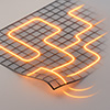
A metamaterial (red) computes a matrix-vector multiplication by decomposing it into elementary operations (blue), corresponding to individual matrix elements. Each elementary operation (purple) is implemented by a metamaterial unit cell. The input vector is presented as a displacement applied on the input control rods (orange, xi) and the result is determined by measuring the displacement of the output rods (blue, yi). Each internal output is connected to an input, ensuring that the resulting metamaterial is frustration-free irrespective of the particular matrix being implemented. (Image: Reprinted from DOI:10.1002/aisy.202500062, CC BY) (click on image to enlarge)
In this study, the device is a thin sheet of rubber cut into a repeating pattern. Displacements applied at selected points along the sheet’s edge move through the structure along planned floppy paths. The resulting movement at other edge points matches the output of a predefined matrix applied to the input vector. Certain internal parts can be switched after fabrication to change matrix entries. The material itself carries out the mapping through its motion, with no intermediate conversion step.
The structure represents the matrix as a grid of small units called tiles. Each tile has two input displacements and two output displacements. It performs a linear mapping, so doubling an input doubles its output, and adding two inputs adds their outputs. Tiles connect edge-to-edge so that the outputs of one tile become the inputs of another.
Inputs are horizontal or vertical displacements applied at the boundaries. Outputs are read as the resulting boundary displacements at the other end. Inside each tile, thin beams and pin joints restrict motion to two floppy modes. These modes define the only low energy deformations that the tile can produce.
Each tile has a coefficient that behaves like a matrix weight. This weight is set by the angle of specific beams and can be positive or negative. When tiles meet, the shared points must move in the same way, which links their floppy modes. The full grid has a direction through which motion flows from inputs to outputs and no loops, so no extra floppy modes appear. The result is a material that copies, scales, and adds motions in the same sequence used to multiply a matrix by a vector.
The tile design starts from an ideal model. In this model, each connection is treated as a rigid rod that only allows movement along its length. A rod between two points limits their relative movement to its axis. A rod between a point and a fixed base allows motion along a single direction.
The Maxwell Calladine theorem predicts how many floppy modes remain based on the balance of movable points and constraints. In the starting layout, there are 18 possible low energy motions. The designers add 16 independent rods to reduce this to two floppy modes. One passes a horizontal input along a path. The other combines horizontal and vertical inputs using angled connectors to create a new displacement. Any input pair can be represented as a combination of these two modes in the ideal case.
Real beams bend and stretch, adding resistance to deformation. These effects reduce how much input motion reaches the output and limit the maximum weight of a tile. To capture these effects, the study uses a three-dimensional finite element model. A finite element model divides the tile into many small parts and computes how each part deforms under force.
The authors define a loss function that measures how far the current mapping is from the desired mapping. They use automatic differentiation to compute how changes in geometry affect this loss. Automatic differentiation applies the chain rule to calculate exact derivatives through each step of the numerical simulation.
To simplify the problem, they use Guyan condensation. This method removes internal nodes and keeps only those at the boundary that define the input-output mapping. Reduced stiffness matrices for each component are assembled to represent the entire tile.
The analysis shows that beam aspect ratio is a key limit. Aspect ratio is beam length divided by beam width. In the ideal model, large beam angles could create large weights. In real beams, large angles increase stiffness along the input path, cutting down how much motion reaches the output. This caps the weight.
The paper estimates the minimum aspect ratio needed to build matrices of different sizes within a given accuracy. The relation is nearly linear. Current microfabrication can produce beams with aspect ratios near 1000 to 1. With that capability, the study finds that matrices larger than 64 by 64 are possible within the target accuracy. That is enough to support tasks like speech feature processing, which use input vectors of around 39 values. These results define clear targets for fabrication and suggest when finer machining could expand the range.
The study tests a prototype. The team cuts tiles from 6-millimeter-thick rubber using water jet machining. Stepper motors apply small, repeated boundary motions. A camera tracks marked points using optical flow, a method that estimates motion by detecting pixel shifts in images.
A single tile produces outputs that match the ideal linear rule within about twenty percent for small inputs. Larger inputs cause saturation. In saturation, the output stops increasing in direct proportion to the input. The curve resembles a sigmoid, which rises quickly then flattens out. In the tile, this shape comes from beams entering a stiffer region of deformation.
The tile also shows hysteresis, meaning that its output during loading differs from its output during unloading. The gap is smaller at slower input speeds, consistent with the viscoelastic behavior of rubber. A two-by-two tile grid produces a full two by two matrix with around twelve to fifteen percent error in the linear range and shows the same saturation and hysteresis. These results confirm that the mapping works within the limits set by beam stiffness and damping.
The study also shows how to change a tile’s weight after fabrication. The designers add extra beams at the point that sets the weight. These beams connect to bistable variable stiffness mechanisms. A bistable mechanism has two stable states. A variable stiffness mechanism can switch between low and high resistance to motion.
In the low stiffness state, the beam adds no constraint. In the high stiffness state, it adds a constraint and changes the weight. In tests, the weight switches among values near plus 0.25, zero, and minus 0.33. Activating both beams overconstrains the tile and removes the mapping. Deactivating both underconstrains it and also removes the mapping. With one beam active, two floppy modes remain, and the tile still functions.
This switching adds slack that increases hysteresis, which future designs might reduce. The result shows that some matrix entries can be changed without rebuilding the material.
The simulation process supports further improvements. Each component is defined by a small set of geometric values. A mesh is generated, reduced stiffness is calculated, and the full structure is assembled. With JAX for automatic differentiation and FEniCSx for finite element analysis, gradients of the mapping error can be computed and passed back to the geometry. A projection step maintains connections during updates.
This turns the design task into a repeatable optimization loop rather than manual tuning.
As this study shows, the patterned rubber sheet performs matrix vector multiplication in its linear range, identifies the cause of nonlinear effects, and allows some weights to be altered after fabrication. The approach uses standard fabrication tools, numerical simulation, and mechanical design. Beam size limits matrix scale. Material damping affects precision and may require slower actuation or different materials. Within these constraints, the study demonstrates a deformable material that performs a core mathematical operation without converting motion into electrical signals.
For authors and communications departmentsclick to open
Lay summary
Prefilled posts
Nanowerk Newsletter
Get our Nanotechnology Spotlight updates to your inbox!
Thank you!
You have successfully joined our subscriber list.
Become a Spotlight guest author! Join our large and growing group of guest contributors. Have you just published a scientific paper or have other exciting developments to share with the nanotechnology community? Here is how to publish on nanowerk.com.